Lab 6: Op Amps -- Part III
Negative-Impedance Converters and General Impedance Converters
This lab demonstrates two novel uses of op-amps -- as negative impedance converters (NICs) and general impedance converters (GICs). To understand how these circuits work, you need to analyze them for sinusoidal steady state operation or in the s domain.
A. Negative-Impedance Converters
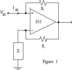
1. A NIC uses an op amp and resistors to produce an input impedance of Zin = -Z. Before coming to lab, analyze the circuit in figure 1 to show that it is a negative impedance converter (i.e., show that Iin = -Vin/Z).

2. Design and build a NIC with Zin = -10 kohm. Use a 355 op amp and whatever resistors you need. (What determines the size of the unspecified resistors R?)
3. Put 20kohms in series with your -10kohm NIC and take measurements to verify that the NIC really behaves as -10kohms.
B. General Impedance Converters
4. A GIC is built with two op amps and five impedances. Figure 2 shows a GIC. Before coming to lab, use circuit analysis to show that:

5. To show that this circuit works, build a GIC to simulate a 10 kohm resistor. Use two 355 op amps and five resistors. Use this simulated resistor in series with a real 10 kohm resistor to build a voltage divider as shown in figure 3. Drive the voltage divider with a 1 kHz, 1V Peak to Peak sine wave. Does the output look like what you would expect?

6. A typical use of GICs is to simulate an inductor. Show that if Z2 or Z4 is a capacitor and the other impedances are resistors, then Zin is the impedance of an inductor. (GICs are used to simulate inductors because it is virtually impossible to build an inductor as part of an integrated circuit, but easy to build op amps, capacitors and resistors.) Modify your circuit from Part 5 so your GIC acts like a 10 H inductor.
7. Use your ``ideal'' inductor in the RL circuit shown in figure 4. Determine the time constant. (Use a square wave with a period of 10 "tau", and measure the 10 % to 90 % rise time. From this, calculate "tau".) Show that this is the time constant you would expect if the inductor and resistor were both ideal. Increase the amplitude of the input voltage until the output becomes distorted. Why does the simulated inductor depart from the ideal response?
