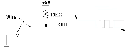
Connect a "switch" as shown in Figure 1. For this lab just use a wire as the switch, and plug it into a GND hole to bring the output of the switch low, and unplug it to bring the output high.

Figure 1: A simple switch.
- Build the switch of Figure 1. Test the circuit with a logic probe. Make sure it works -- with the wire in, the output should be low; with the wire out, it should be high.
- Connect the output of the switch to one channel of your logic analyzer. Set up the logic analyzer for a 1 MHz internal clock. Start with your switch closed (wire in the GND hole). Click on the green GO button, pull the wire out, and see if you can observe switch bounce.
-
You couldn't see the switch bounce in the above part because the logic analyzer
is much faster than you are. By the time you pulled out the wire after you
pressed the GO button, the analyzer had already finished sampling,
so you were not able to observe the low-to-high transition of the switch.
In order to observe this transition you need to have the logic analyzer stop
shortly after this transition. Making the logic analyzer stop after observing
a desired pattern is called triggering. To trigger the logic analyzer
on the low-to-high transition of your switch, do the following:
- Double click on the Trigger Patterns Window icon. Set pattrn01 for a value of 1 for your input line. This means that the logic analyzer will continue to sample until this line goes high. After the line goes high, it will sample for a while longer, then show you your logic trace both before and after the trigger condition.
- Minimize the Trigger Pattern Window. Click on the green GO button. The logic analyzer should continue running.
- Pull the wire out of the GND hole. The logic analyzer should stop, and display the switch bouncing.
- Capture the waveform for several switch bounces. How many bounces do you typically get? What is the typical length of a bounce? From the initial low-to-high transition, how long does it take the switch to reach a constant high value?
-
Set the logic analyzer to trigger on the high-to-low transition, and repeat
the above part.
Build a circuit similar to the one shown in section 10.3.4 (pp.
645-655) of Brown (use 10 k Ohm resistors) using NOR gates (74HC02 chip).
Note that you will need to use pull-down resistors (not pull-up) and the
end of the wire to +5V (not GND). Use a wire to simulate your switch. Connect
the R, S, Q and Q' signals to your logic analyzer.
Trigger your logic analyzer on the high-to-low transition of Q, and
observe the outputs when you toggle your switch. Repeat for the low-to-high
transition. Does this circuit eliminate the bouncing? Be sure to plot your
results.
Replace the pull down resistors, used in part 2, with the stimulus generator which you designed in the prelab to drive the R and S inputs, and look at R, S, Q, and Q' on your logic analyzer. Make sure that you test all possible transitions, not just all possible combinations of inputs. Verify that your latch works. What happens when SR changes from 11 to 00? Be sure to plot your results.