EE 212 Lab
Lab 5: Power Factor Correction
Prelab 5
Recall that average power absorbed by a circuit element is
VrmsIrmscos(¸) where ¸ is the phase difference
between the element's sinusoidal voltage v(t) and current i(t). To obtain
the most efficient use of the current delivered to a load, it is desired
that the load voltage and current be in phase (¸ = 0, pf = 1) such that
average power is maximized. The purpose of this lab is to add compensation
to an inductive load such that its equivalent power factor becomes close
to 1.
Notes on Measurements:
-
Experimental determination of the power factor typically requires the measurement
of the phase difference between voltage and current. Two properties of the
function generator and oscilloscope make this measurement difficult.
-
The reference (ground) leads on the oscilloscope and function generator are
internally tied to ground making it imperative that they all be connected
to the same point in the circuit.
-
The difference between channels 1 and 2 (CH1-CH2) can only be displayed by
itself on the oscilloscope.
-
Carefully consider where to take measurements such that subject to the above
constraints the information of interest can be determined.
Laboratory Procedure:
-
Investigate inductive load
-
An inductor is a coil of wire and wire has resistance. Measure the resistance
of your 0.47mH inductor. If this resistance is significant include it your
calculations.
-
Construct the following circuit.

-
Experimentally determine the load impedance ZL, power factor angle
¸, power factor, and complex power using voltage and current measurements.
Compare these to your predicted values found in the prelab.
-
Load power factor correction
-
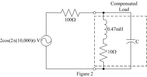
Add a capacitor of the value determined in the prelab in parallel with the
original load as shown in figure 2. Note the value of the capacitor may need
to be updated based upon the resistance of the inductor.

-
Verify that your power factor correction is working. Due to the measurement
constraints described above, it might be easier to verify your power factor
correction by comparing the load voltage to the source voltage. What should
this relationship be and how does it compare to your experimental results?
-
Normally, it isn't a good idea to change a circuit with input and power applied,
but carefully insert and remove the capacitor while watching the source and
load voltages to easily see the effect of the compensation.
-
Does your load compensation work at other frequencies other than 10kHz?
Investigate this both mathematically and experimentally. Is there a difference
in the load as frequency is increased versus decreased?
© Copyright 2004 New Mexico Institute of Mining and Technology

