In this lab the step response of a series RLC circuits will be generated and studied.
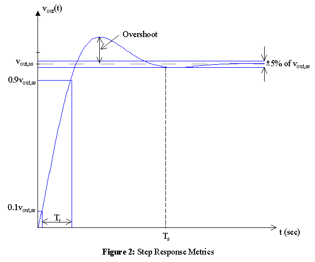
Step response metrics are shown in firgure 2. The table below will
be filled in with these metrics for the RLC series circuit that you will
design and build for this laboratory.

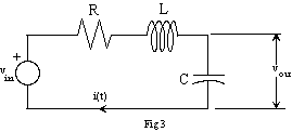
Determine values of R, L, and C for the circuit shown in figure 3 so that
the step response is a damped sinusoid with an exponential decay governed
by an a of 105 (i.e. the damped
sinusoidal response goes to e-1 of its final value in 10
m-seconds) and an undamped natural frequency of
1MHz. Use the value of L in your parts kit, i.e., the nominal 0.47mH inductor.

Observe the step response and compare the theoretical response with your measurements in a table similar to that shown below. For this underdamped RLC circuit, the response should have the form
vout(t) = vout,ss (1 - Ke-atcos(wt + q))u(t).
| Predicted | Measured | |
| Initial Value, vout(0) | ||
| Final (steady-state) Value, vout,ss = vout(¥) | ||
| 10% - 90% Rise Time, Tr | ||
| (Within 5%) Settling Time, Ts | ||
| Percent Overshoot, 100%(peak value - vout,ss) / vout,ss | ||
| a | ||
| w |