EE 321 Lab
Lab 1: Amplifiers, Biasing, and AC Coupling
The purpose of this lab is to measure the characteristics of an amplifier,
and to use the characteristics to add a bias circuit at the input. We will
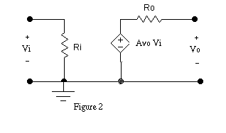
represent the same amplifier three different ways. These are a block diagram,
a model, and a schematic of the components. Figure 1 shows the block diagram
of a generic amplifier. Figure 2 shows the model for a voltage amplifier.
The characteristics which we need to measure are Ri, Ro
and Avo.
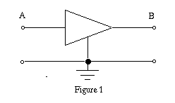
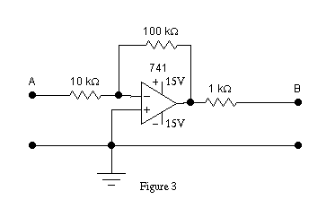
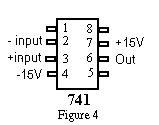
We will use the circuit in Figure 3 as our amplifier. (Use a 741
or similar op-amp; the 741 pin out is shown in Figure 4.) In Figures 1,
2 and 3, the input to our amplifier is at A and the output at B. If we
can find the three values Ri, Ro, and Avo
we can use the model to accurately predict how the amplifier will work
in a circuit.
-
Build the amplifier.
-
From your knowledge of op amps, you may be able to determine Ri,
Ro and Avo from inspection of Figure 3. If you remember
how calculate the values so you can compare them to the values you measure
below.
1) Measure the transfer function, Avo, of the amplifier in
the following manner.
-
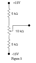
Connect the variable voltage source of Figure 5 to the input, and measure
the voltage at both the input (A) and output (B) with a DVM. Plot the input
voltage versus the output voltage. The gain, Avo, is the slope
of this line.
-
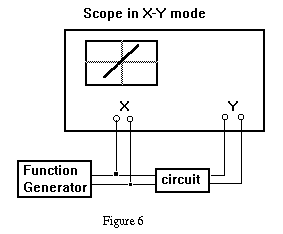
This process can be automated. Use the function generator and scope
to trace the transfer function as shown in Figure 6. Store and copy the
X-Y plot. Carefully mark the scales just as on the first graph.
-
Compare your curve with the X-Y plot. What are the saturation voltages
for the output?
2) Determine the input resistance Ri of the amplifier model
circuit (that is the resistance from point A to ground).
-
To do this add a test resistor between the variable source and the input
(A).
-
Make sure the output is NOT saturated.
-
Measure the voltage of your variable source, and the voltage at point
A.
-
From a drawing of the input input circuit connected to the amplifier
model you can see how Ri effects these voltages. Compute Ri.
-
If the test resistor is not within a factor of 2 of Ri, change
it to one about equal to Ri and make a more accurate determination
of Ri. Why does this make the determination more accurate.
-
Measure the test resistor with an ohm meter to determine its value accurately.
-
Why can't you use an ohm meter to find Ri?
3) Determine the output resistance Ro.
-
Using a short to measure isc may damage an actual amplifier,
so in general, you should not short the output to try to measure Ro.
-
Instead place a load resistance from B to ground, and note the decrease
of the output voltage.
-
To see how to analyze this, draw the output half of the amplifier model
including the test resistor, marking measured voltages.
-
Choose a test resistor of an appropriate size. (What is an appropriate
size?)
-
Compute Ro.
4) A capacitor will block DC voltages.
-
Input a 5 kHz, 1V p-p sine wave. Display and sketch the input and output.
-
Use the function generator to add a 0.1 V offset to the input. What
is the effect at the output?
-
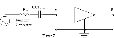
Add a 0.015 mu capacitor as shown in Figure 7 (Rs is the
source resistance of the signal generator). How is the output affected.
-
Why?
-
What effect does varying the input offset have on the output voltage?
5) Biasing the amplifier.
-
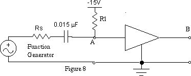
Add the bias resistor R1 shown in Figure 8 to change the
output operating point to about 5V
-
For an input vi of 0V the output vo should be
5.0V .
-
The resistance values determined for the model can be used to calculate
R1.
-
With a sine input, sketch the output.
-
What is the effect of the biasing on the output?


