
EE321 Lab #9
MOSFET II
The purpose of this lab is test several MOSFET circuits The CMOS 4007 integrated circuit contains 6 MOSFET's 3 n-channel and 3 p-channel. The n-channel bodies are connected to pin 7 and must be kept at the most negative voltage used in the circuit. The p-channel bodies are connected to pin 14 and must be kept at the most positive voltage used in the circuit. The drain and source are interchangeable on Q2 and Q5.
Anti-static precautions must be taken!
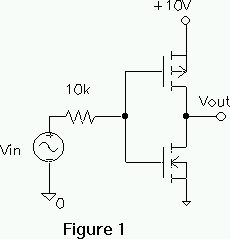
1. Build the CMOS inverter (Figure 1). The input should be preset to go from 0 to 10 V. The input resistor protects diode junctions that would be forward biased if the input exceeds its range.


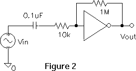
2. Add a feedback resistor and input capacitor to make a small signal amplifier (Figure 2). The large resistor causes the input and output to be equal at low frequencies causing the bias to be in the center of steep portion of the transfer curve, at the point of high gain. The feedback is not enough to effect the mid frequency gain.
3. Test the circuit to find the small signal gain.
MOSFET POWER SWITCH
4. Design build and test a MOSFET circuit turns on and off a lamp.

5. Connect the input to keep the lamp on with 5 V across it.
CURRENT MIRROR
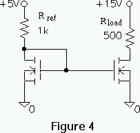
6. Build and test the current mirror shown in Figure 4, using a 4007.
