Design your H-Bridge motor controller. There should be two inputs that go from 0 to 5 V. One is a PWM signal the controls the motor speed. The second determines the motor direction. Other inputs are DC power supply voltages. The two outputs will hook to either side of the motor. The motor needs 12 to 15 V to run well.
The purpose of this lab
is to investigate circuitry which is useful for constructing solid-state
controllers for permanent-magnet DC motors.
Flyback Voltage.
Some interesting things
happen when an inductive load such as a motor is switched on and
off suddenly. To see some of these effects, we will use the single-sweep
and storage capabilities of our oscilloscopes to capture the transients
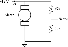
associated with turning a small motor off. Construct the
circuit shown below and connect it to the oscilloscope as indicated.

Put the oscilloscope into
single sweep mode. Set the vertical scale
to 5 V/div and the time scale to 0.1 ms/div. Use DC-coupled
triggering, normal trigger mode,
and play with the trigger level setting it just below the point where it will
normally trigger. Disconnect the 15 V at point A.
You should see a negative spike.
Record one of the more
spectacular transients for your notebook. How big is this at the motor?
Describe at least one
way that such transients could damage a switch, especially if
it were a solid-state switch.
To combat the negative
transients, put a 1N5818 Schottky diode in parallel with the
motor (it should be reverse biased when the power is on). Repeat
the observations made above to see the effect of the diode.
A MOSFET On/Off Switch.
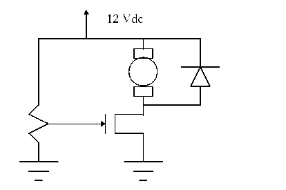
Use an IRF711 N-channel
MOSFET to build the following circuit.
At what gate voltage will
the switch turn-on? Measure a few points and plot of the drain-source voltage as
a function of the gate-source voltage during steady-state operation.
What would the drain-source voltage be ideally when it is on? What range of
gate-source voltages will produce "reasonable" values?
Replace the potentiometer
with a TTL-level ( 0-5 volts) square-wave generator set at 10
kHz. Use the oscilloscope to display the waveform of the motor
voltage. Reduce the square-wave frequency gradually to a few hertz
and observe the motor response. Explain what happens.
Pulse-Width Modulation
(PWM) Controller.
We can vary the average
voltage seen by the motor by controlling the duty cycle of the
square-wave applied to the MOSFET gate. Use the variable pulse width
feature on your function generator. Use a 1 kHZ frequency. As you
vary the pulse width the motor speed and voltage should should change
proportionately. Monitor the motor voltage with your scope.
H-Bridge Controller
Design and build an H-Bridge Controller for your motor. Inputs should be the PWM 0-5 V signal and a
direction signal that is 0 or 5 V.

