The purpose of this lab
is to investigate circuitry which is useful for constructing solid-state
controllers for permanent-magnet DC motors.
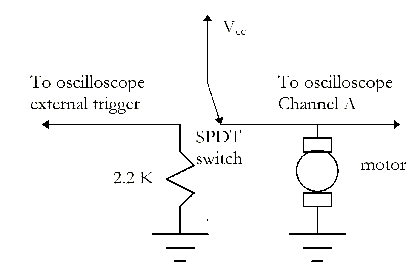
Flyback Voltage.
Some interesting things
happen when an inductive load such as a motor is switched on and
off suddenly. To see some of these effects, we will use the single-sweep
and storage capabilities of our oscilloscopes to capture the transients
associated with turning a small motor on and off. Construct the
circuit shown below and connect it to the oscilloscope as indicated.
Put the oscilloscope into
storage mode and set it for single sweep. Set the vertical scale
to 10 V/div and the time scale to 0.1 mS/div. Use DC-coupled external
triggering and play with the trigger level until throwing the
switch reliably starts the motor and triggers the 'scope. You
will see a series of fast on-off cycles associated with closing
the switch: these are caused by contact bounce in the mechanical
switch. What happens to the voltage across the motor as a result
of this contact bounce? Can you see similar transients associated
with turning the motor off? Why or why not? Print one of the more
spectacular transients for your notebook. Describe at least one
way that such transients could damage the switch, especially if
it were a solid-state switch.
To combat the negative
transients, put a 1N4007 rectifier diode in parallel with the
motor (it should be reverse biased when the power is on). Repeat
the observations made above to see the effect of the diode.
A MOSFET On/Off Switch.
Use an IRF711 N-channel
MOSFET to build the following circuit. "Float" the power
supply so that the oscilloscope ground may connected to any arbitrary
point within the circuit.
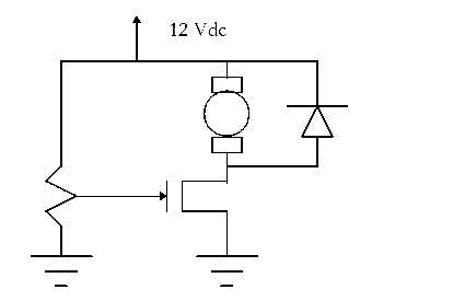
At what gate voltage will
the switch turn-on? Make a plot of the drain-source voltage as
a function of the gate-source voltage during steady-state operation.
What would the drain-source voltage be ideally? What range of
gate-source voltages will produce "reasonable" values?
Replace the potentiometer
with a TTL-level ( 0-5 volts) square-wave generator set at 10
kHz. Use the oscilloscope to display the waveform of the motor
voltage. Reduce the square-wave frequency gradually to a few hertz
and observe the motor response. Explain what happens.
Pulse-Width Modulation
(PWM) Controller.
We can vary the average
voltage seen by the motor by controlling the duty cycle of the
square-wave applied to the MOSFET gate. An effective PWM circuit
can be made from a 555 timer chip as shown below. This circuit
is a monostable which produces an output pulse whenever the trigger
input falls below 1.6 V. The duration of the output pulse is
T = 1.1RC. We will play with the 555 timer in more detail
in a later lab.
Use the 10 kHz TTL square-wave
as your trigger voltage. To achieve duty cycles ranging up to
90%, we will need output pulse durations of up to 90 microseconds.
Choose C so that a 10 kilohm pot can be used to vary the duty
cycle within this limit.
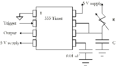
Construct the circuit.
Adjust the pot until you get a 50% duty cycle, then measure the
resistance of the pot. Does the value match your theoretical expectations?
Use the circuit to drive the gate of the MOSFET switch. Measure
the motor voltage with a multimeter. You should be able to smoothly
vary the motor voltage by adjusting the duty cycle via the pot.