-
A TDF using a factored form of the Boolean logic shown in Figure 5.4(b),
page 225 of Brown (cout=ci+1):
SUBDESIGN fulladdr ( a,b,cin : INPUT; sum,cout : OUTPUT; ) BEGIN sum = (a $ b) $ cin; cout = ((a # b) & cin) # (a & b); END; -
A TDF using if-then structure:
SUBDESIGN fulladr ( a,b,cin : INPUT; sum,cout : OUTPUT; ) BEGIN if (((0,cin)+(0,b)+(0,a)) ==0) then (cout,sum) = 0; elsif (((0,cin)+(0,b)+(0,a)) ==1) then (cout,sum) = 1; elsif (((0,cin)+(0,b)+(0,a)) ==2) then (cout,sum) = 2; elsif (((0,cin)+(0,b)+(0,a)) ==3) then (cout,sum) = 3; end if; END; -
A TDF using arithmetic operations:
SUBDESIGN fulladr ( a,b,cin : INPUT; sum,cout : OUTPUT; ) BEGIN (cout,sum) = (0,cin)+(0,b)+(0,a); END; -
A TDF using a truth table Figure 5.4(a), page 225 of Brown:
SUBDESIGN fulladr ( a,b,cin : INPUT; sum,cout : OUTPUT; ) BEGIN TABLE cin, b, a => cout, sum; 0, 0, 0 => 0, 0; 0, 0, 1 => 0, 1; 0, 1, 0 => 0, 1; 0, 1, 1 => 1, 0; 1, 0, 0 => 0, 1; 1, 0, 1 => 1, 0; 1, 1, 0 => 1, 0; 1, 1, 1 => 1, 1; END TABLE; END; -
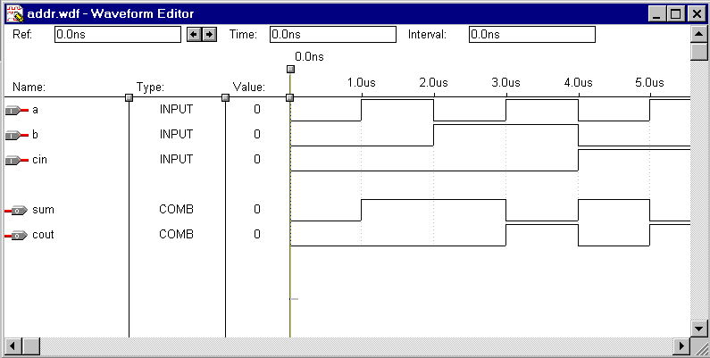
You could also enter the design as a waveform using the Altera Waveform Editor
to enter a Waveform Design File

(See Altera Max+Plus II Getting Started online help to see how to do this.)
- Another way would be to use the Graphical Editor to enter the gate representation shown in Figure 5.4(c), page 225 of Brown, in a Graphic Design File (GDF). (Details on using the Graphical Editor are discussed below.)
In an open area of the Graphical Editor, double-click with the left mouse button. In the Enter Symbol dialog box, enter the name of your 1-bit full adder (fulladdr.sym). Repeat this until you have four full adders displayed vertically.
In the empty space to the left of the full adders double-click the left mouse button. In the Enter Symbol dialog box, enter INPUT in the Symbol Name box, and choose OK. The INPUT symbol is then displayed.
Press left mouse button to select the INPUT symbol then use the right mouse button to create a copy (then paste) of the symbol and place it below the original. Repeat until you have eight inputs.
Repeat the above steps to create five outputs using the OUTPUT symbol.
Point to one of the input pins and double-click the left mouse button. Type the name you wish to give this input (e.g., A0. Repeat until all eight inputs (A0-A3 and B0-B3) are named. Do the same for the five outputs (S0-S3 and Cout).
The Cin input to the first 1-bit adder needs to be connected to GND. Double-click the left mouse button near the Cin input of the first adder and choose the symbol GND.
Connect the input symbols to the inputs of the full adders, and the outputs from the full adders to the output symbols. Also cascade the cout from one full adder to the cin on the next. Connect the cout from the last full adder to the COUT output symbol. To make connections, point one end of the connection, press and hold down the left mouse button, drag the mouse to the other end of the connection, and release the mouse button.